

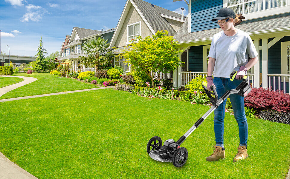

Please Read Before Use. Reserve For Later Use.

|
1 |
Lawn mower |
1 pc |
|
13 |
Grass rope |
8 pcs |
|
2 |
Protective cover |
1 pc |
|
14 |
Dust cover |
1 pc |
|
3 |
Wheel |
2 pcs |
|
15 |
Nuts |
1 pc |
|
4 |
Side wheels |
1 pc |
|
16 |
Lower pressure plate |
1 pc |
|
5 |
Charger |
1 pc |
|
17 |
Storage bag |
1 pc |
|
6 |
Battery |
2 pcs |
|
18 |
Screwdriver |
1 pc |
|
7 |
Auxiliary handle |
1 pc |
|
19 |
T-type screwdriver |
1 pc |
|
8 |
Manual |
1 pc |
|
20 |
Long blade |
1 pc |
|
9 |
Anti-collision strip |
1 pc |
|
21 |
Circular blade |
1 pc |
|
10 |
Wheel bracket |
1 pc |
|
22 |
Rounad gasket |
2 pcs |
|
11 |
Grass cutting head |
1 pc |
|
23 |
Screw |
9 pcs |
|
12 |
Upper pressure plate |
1 pc |
|
|
|
|
Mower Head Assembly Steps
1. Insert the protective cover into the green slot on thejimower head in the direction of the arrow and secure it with two screws.

2. Place the dust cover into the mower head, align the holes of the dust cover with the green slots, and secure with three screws.

3. Put the lower pressure plate in, and keep the holes of the lower pressure plate aligned with the holes of the dust cover and the green slots.

4. Place the circular blade into the slot along the clockwise direction, and put the protruding part of the upper pressure plate upward into the slot.

5. Put the mowing head and nut into the slot in order, and tighten the nut counterclockwise by hand.

6. Insert a screwdriver into the hole of the dust cover to fix it.

7. Keep the screwdriver inserted into the hole of the dust cover, and use the hexagonal side of the T-type screwdriver to insert the nut and tighten the screw counterclockwise.

Please view the instruction video in this link or scan the QR Code.
Product Link:https://www.youtube.com/watch?v=Yz1G9x5BRD4

Most users read:
- 3 Best Cordless Tillers for Your Small Garden 2026: Top Picks & Buying Guide
- 3 Best Cordless Weed Eater for Small & Medium Garden
Main Auxiliary Wheel Installation
1. Please prepare 2 wheels, 1 wheel bracket, 2 round washers, 4 screws and a screwdriver.

2. Please insert the protruding part of the wheel bracket into the hole on the concave side of the wheel.

3. Place the round washer and screw on the other side of the wheel and tighten with a screwdriver (follow the same steps to install the wheel bracket on the other side).

4. Please insert the assembled wheel bracket into the green slot on the mower head.

5. Use screws to fix in the holes to complete the overall assembly.

Side Wheel Installation
1. Please prepare 1 side wheel and mower head.

2. Please distinguish the front and back sides, the picture shows the back side.

Method 1: Insert the side wheel with the reverse side facing down into the slot with the metal sheet to complete the installation of the side wheel.

Method 2: Please insert the reverse side of the side wheel into the slot with metal sheet according to the direction of the picture to complete the installation of the bottom auxiliary wheel.

Auxiliary Handle Assembly Steps
1. Please prepare the auxiliary handle.(The width of the auxiliary handle is slightly narrower than the width of the green button to prevent it from falling off easily after installation.)

2. Please distinguish between green button ①, green button ② and auxiliary handle slot ①, slot ②.

3. Press and hold button ① and button ②, push the auxiliary handle slot ① into button ①, and the slot ② into button ②, until a "click" sound is heard and the green button pops up normally, the auxiliary handle is assembled.

Battery Assembly Steps
1. When installing the battery pack, align the spring ② on the battery pack with the groove ① on the outer cover.

2. Push it in the direction of the arrow.

3. The battery pack will lock with an audible click when fully inserted.

Disassembly Tips: To remove the battery pack, press the button on the front of the battery pack while pulling the battery pack out of the tool.

Long Blade Assembly Steps
1. Insert the protective cover into the green slot on the mower head in the direction of the arrow and secure it with two screws.

2. Place the dust cover into the mower head, align the holes of the dust cover with the green slots, and secure with three screws.

3. Put the lower pressure plate in, and keep the holes of the lower pressure plate aligned with the holes of the dust cover and the green slots.

4. Place the long blade into the slot and place the protruding part of the upper pressure plate upward into the slot.

5. Put the mowing head and nut into the slot in order, and tighten the nut counterclockwise by hand.

6. Insert a screwdriver into the hole in the dust cover to secure it, and use the hexagonal edge of the T-type screwdriver to insert the nut.

7. Turn the T-screwdriver counterclockwise to tighten the nut.

Steps For Assembling The Grass Rope
1. Insert the trimmer rope into the hole under the trimmer head from the outside until it reaches a quarter of its length.

2. Pass the insert part through the second hole above and straighten it. Assemble the other side of the mower head in the same way.

3. Insert the protective cover into the green slot on the mower head in the direction of the arrow and secure it with two screws.

4. Place the dust cover into the mower head, align the holes of the dust cover with the green slots, and secure with three screws.

5. Put the lower pressing plate in and align the holes of the lower pressing plate with the holes and green slots of the dust cover, and put the upper pressing plate on the lower pressing plate.

6. Put the assembled mowing head into the slot and secure it with the nut.

7. Insert the screwdriver into the hole of the dust cover and tighten the nut counterclockwise with a T-type screwdriver to complete the final fixation.

|
Product Specifications |
||
|
No-load speed (not include cutting tools) |
22000r/min |
|
|
Total length (not include cutting tools) |
55.11 inch |
|
|
Diameter of nylon wire |
9 inch |
|
|
Applicable cutting tools and cutting diameters |
Diamond blade length |
9 inch |
|
Rated voltage |
21v |
|
|
Standard battery |
21v |
|
|
Net weight |
6.17 LBS |
|
Precautions:
1. Be familiar with the controls and proper operation of the tool. Keep your fingers away from the switch trigger when not operating the tool and when moving between operating positions.
2. Do not allow children or people who are not familiar with these instructions and operation to use this machine.
3. Do not use this machine near people (especially children) or pets.
4. Do not operate the tool when tired, unwell or under the influence of alcohol or drugs.
5. The machine can only be used in bright or well-lit conditions. Avoid using the machine in bad weather (especially thunderstorms).
6. Before using the machine, after the machine is hit, and if the tool shows signs of operating failure, the machine should be turned off and inspected for wear or damage immediately, and repaired if necessary.
7. Be careful not to be cut by the mowing line. After extending the new cutting line, always return it to its normal working position before turning the device on.
8. After the motor is turned off, the cutting parts will continue to rotate to prevent cuts.
Maintenance Instructions:
1. Before starting work, check the condition of the tool, protective gear and shoulder strap.
2. Before carrying out maintenance, changing tools and cleaning tools, switch off the motor and remove the battery pack.
3. Check whether the fastenings are loose or parts are damaged, such as cracks on the tool.
4. When not in use, store the device in a dry place out of the reach of children and lock it.
5. Keep the vents free of debris and the handles dry, clean and free of oil and dirt.
6. Check and maintain the tool regularly, especially before and after use.

Share:
Top 5 Must-Have Electric Gardening Tools for Effortless Yard Work
3 in 1 Grass Trimmer Instruction Manual